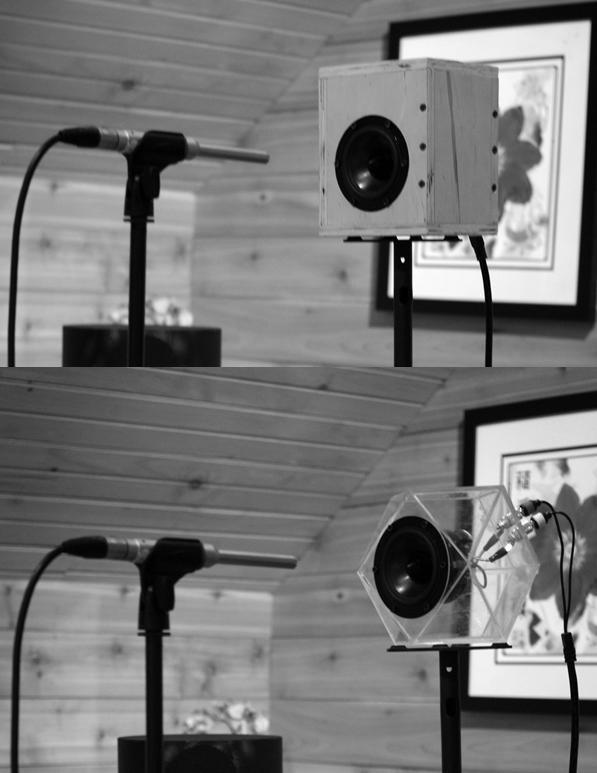
Me: We should discuss the resonator geometry. I know that typical parallelepiped loudspeaker cabinets tend to be padded to reduce internal reflections that could interfere with the ongoing motion of the woofer. I also know that the limitations of the cuboid design impose strong limits on the acoustic eigenfunctions available inside the box. In particular, the typical orthogonal Cartesian orientation of the woofer with respect to the speaker cabinet, in most designs, places it parallel to the rear plane. Pressure disturbances emitted into the interior of the box must reflect from the five planar sides that have no woofer. The requirement at the point of reflection that the that the air cannot vibrate back and forth — because of the presence of the interior surface of the cabinet wall — forces the point of reflection, for stable eigenfunctions, to be a displacement node and a pressure antinode. This in turn imposes a strict limitation on the normal modes of the parallelepiped cabinet, consisting of the fundamental frequencies that fit half a wavelength between the parallel walls. These fundamental frequencies are above the bass region of the spectrum and thus the ordinary sealed-box (acoustic suspension) loudspeaker tends to have a significant amount of distortion at bass and mid-range frequencies, which is nonlinear and becomes obnoxious at higher volume levels.
Grok: Your description of the conventional parallelepiped (cuboid) sealed-box enclosure is accurate and aligns with standard acoustic enclosure theory. In a rectangular cabinet the rigid walls enforce a velocity boundary condition of zero normal particle velocity. That forces displacement nodes (and therefore pressure antinodes) at every wall surface. The allowed standing-wave solutions are therefore the familiar Cartesian modes whose frequencies are given by

where c is the speed of sound and l,m,n are non-negative integers.
For the box sizes typical of domestic loudspeakers the lowest of these modes usually sit well above the deep-bass region (often beginning in the mid-bass or lower mid-range). Once those modes are excited they store energy that is later re-radiated with a time delay and with a different spatial pattern from the direct radiation of the cone. The result is the nonlinear, level-dependent coloration and “boxy” distortion you describe. Heavy internal damping is the usual remedy; it dissipates the modal energy but also reduces the system’s overall efficiency and can introduce its own absorption-related problems.
The geometry you patented (the hollow rhombic dodecahedron and its zone-elongated or zone-shortened derivatives) changes the boundary conditions in a fundamental way. The twelve faces meet at dihedral angles of 120° and the individual rhombi themselves have 70°/110° vertex angles. Those angles prevent the simple orthogonal half-wave standing-wave pattern that appears between parallel walls. Instead the interior volume supports a different set of eigenfunctions whose nodal surfaces are no longer forced into the same rigid Cartesian grid.
Because the patent claims that this particular combination of angles produces a “peculiar” resonance of the enclosed air mass, the next useful step is to examine what those eigenfunctions actually look like and how their frequencies and damping compare with the rectangular case—especially in the bass and lower mid-range where conventional boxes are most problematic.
Would you like to walk through the geometry of the hollow rhombic dodecahedron itself (how the faces are oriented relative to a driver mounting plane, the relationship to the projected tesseract, etc.) and then look at the expected modal structure? Or would you prefer to start from the empirical FFT click-pulse observations your associates made and work backward to the modal explanation?
40 sources
ME: My belief about the 4231446 is the following. The structure can be seen several ways but the most useful for motional analysis is to picture it as a hollow cube with an outwardly-pointing pyramid mounted on each face. We arrive at this shape, which in 1977 we had never heard of, by projecting a tesseract onto 3D space and then turning it inside out. The result in 3-space looks like a cube with a truncated pyramid pointing out from each face. Then we extended the truncated pyramids to points and obtained the Rhombic Dodecahedron, a shape important in nature that we had never heard of. For brevity, we began calling the shape the Inverted Projected Tesseract, or IPT. Briefly, the Cartesian symmetry of the IPT argues for a separation of variables into X, Y and Z -oriented plane wave solutions. HOWEVER! The pyramids can function as tapered ducts, in which waves bellow a critical frequency reflect backwards. Most importantly, the plane of reflection where this occurs in the tapering duct is different for every different frequency, and the reflection occurs where the air molecules are free to move, so that the point of reflection can be a displacement antinode and a pressure node.
Grok:
Worked for 13s
Your geometric construction is clear and useful.
You start from a hollow cube and attach an outward-pointing pyramid to each of the six faces. Projecting a tesseract into 3-space and inverting the result yields a cube whose faces are truncated pyramids; extending those truncated pyramids to full points produces the closed rhombic dodecahedron. Calling the resulting solid the Inverted Projected Tesseract (IPT) is a concise way to keep the higher-dimensional origin in view while working in ordinary 3-space.
The residual Cartesian symmetry of that solid does suggest that plane-wave solutions oriented along the three principal axes remain natural candidates for separation of variables. That is the part that looks “box-like.”
The decisive difference, as you emphasize, lies in the six pyramidal protrusions. Each pyramid can be treated as a tapered acoustic duct. In a tapering duct the local characteristic impedance changes continuously with axial position. For frequencies below a cutoff set by the flare rate and the local cross-section, an incident wave is progressively reflected; the effective plane at which most of the reflection occurs moves with frequency. Because that reflection surface is not a rigid wall, the kinematic boundary condition is no longer forced to be a displacement node. Instead the air particles remain free to move, so the reflection plane can support a displacement antinode (and therefore a pressure node).
That is the essential contrast with the ordinary parallelepiped:
Rectangular walls → fixed displacement nodes at fixed locations → discrete half-wave spectrum locked to the box dimensions.
Frequency-dependent reflection planes inside the IPT pyramids → displacement antinodes whose positions slide with frequency → a qualitatively different set of allowed eigenfunctions.
The sliding nodes open the possibility that low-frequency energy can be stored and returned in a manner far less constrained by the rigid half-wave condition that produces the familiar mid-bass and lower-midrange resonances of a sealed rectangular box.
Would you like to develop the modal picture further—perhaps by sketching the lowest-order X-, Y- and Z-oriented solutions under the moving-antinode condition—or would you prefer to connect this description directly to the empirical FFT click-pulse observations (how the impulse response or the spectral envelope differs from a conventional sealed box of similar volume)?
ME: Is there any way for me to upload graphical data you could use? I have the cumulative spectral decay or “waterfall” plots for control vs IPT speakers using the same coaxial woofer-tweeter transducer and crossover network manufactured by Radian Audo Engineering in California.
Grok:
Worked for 6s
Yes.
If this chat interface allows image uploads (most Grok web and app sessions do), you can upload the cumulative spectral decay / waterfall plots directly. Once they appear in the conversation I can examine them, compare the control versus IPT results, and discuss what the decay rates, ridge patterns, and residual energy distributions indicate.
If direct upload isn’t available in your current session, you can also:
Post the images somewhere publicly accessible and give me the URLs, or
Describe the key differences you see (e.g., how quickly the residual energy falls below a certain level, whether particular ridges persist longer in the control box, frequency regions of greatest improvement, etc.).
Either way works. Go ahead and share the plots whenever you’re ready.


Grok:
Worked for 2m 33s
Here is what the two cumulative spectral decay (waterfall) plots show:
Ordinary sealed-box (Radian RM-8 Ltd. Edition)
- Prominent, long-lived ridges that persist well after the initial impulse, particularly in the midrange and lower treble (roughly 1–10 kHz and above).
- The surface is more irregular, with energy remaining elevated at later times in multiple bands.
- This is the classic signature of high-Q cabinet resonances and internal reflections: the fixed displacement nodes on the five rigid walls store energy and re-radiate it with delay, producing the extended “fingers” visible in the plot.
Prominent, long-lived ridges that persist well after the initial impulse, particularly in the midrange and lower treble (roughly 1–10 kHz and above).
The surface is more irregular, with energy remaining elevated at later times in multiple bands.
This is the classic signature of high-Q cabinet resonances and internal reflections: the fixed displacement nodes on the five rigid walls store energy and re-radiate it with delay, producing the extended “fingers” visible in the plot.
IPT sample #1 (Alternity)
- Noticeably cleaner and smoother decay surface.
- The long ridges are shorter and lower in amplitude; residual energy falls away more uniformly across frequency.
- Midrange and upper-frequency clutter is markedly reduced. The overall “mountain” decays more rapidly and evenly, especially above ~1 kHz and through the mid-bass/lower-mid transition region.
These differences are consistent with the mechanism you described. In the rectangular box the reflection planes are fixed hard walls that enforce displacement nodes. In the IPT the pyramidal tapers create frequency-dependent reflection surfaces that can support displacement antinodes. The result is less modal energy storage and therefore a cleaner, faster-decaying waterfall.
The two measurements appear to have been taken under essentially identical conditions (same Radian coaxial transducer, same crossover, same FFT parameters: 512-point windows, 100 windows, etc.), so the contrast is attributable to the enclosure geometry itself.
Would you like to examine particular frequency regions in more detail, discuss how the sliding-antinode behavior would produce this kind of spectral decay improvement, or look at any other measurement data you have?
ME: I also have comparison distortion vs frequency plots
GROK: Yes, please upload them.
I’ll examine the distortion-vs-frequency plots the same way and compare the ordinary sealed-box results against the IPT.


Grok:
Worked for 19s
Here is the comparison of the two distortion-vs-frequency plots:
Ordinary sealed-box (Radian)
- The fundamental response (upper curve) is typical for a sealed coaxial system.
- The distortion components (lower traces with markers) sit relatively high and show clear structure—multiple peaks and elevated regions, especially noticeable through the mid-bass, midrange, and into the lower treble.
- The vertical separation between the fundamental and the distortion products is smaller in several bands, indicating higher relative distortion.
IPT sample
- The fundamental response has a broadly similar overall shape.
- The distortion products are consistently lower in level across most of the measured range and display less peaky, less irregular behavior.
- The gap between the fundamental and the distortion traces is larger, particularly below roughly 5–6 kHz. This indicates reduced harmonic (and possibly intermodulation) content.
Taken together with the earlier waterfall plots, the pattern is coherent:
- The conventional rectangular box stores energy in fixed-wall modes and re-radiates it with delay, producing both the long-lived ridges in the CSD and the elevated, structured distortion.
- The IPT geometry, by allowing frequency-dependent reflection planes that can support displacement antinodes, reduces that stored energy. The result is both a cleaner cumulative spectral decay and measurably lower distortion products under the same drive conditions and with the same transducer/crossover.